Electrical motors have been used in industries for quite a long period of time to convert electrical energy into mechanical energy. Three phase induction motors, also called asynchronous motors, are most extensively used motors in industries because of certain advantages like self starting, robust design, simple construction, less maintenance, efficient and comparatively low cost, though there is a problem of peak starting current associated with these motors. Peak starting current can be up to 5 to 7 times of full load current (flc) and sometimes it may become as high as 10 times of flc. However, the problem of peak starting current remains only for few seconds till the motor attains its speed, this problem may become severe especially with the motors above 10 HP. To deal with the problem of peak starting current or inrush current associated with three phase induction motors, many different starters having different mechanism and principle of operation are used. Star-delta starters are used for motors ranges from 5 hp or 3.5 kW. Star delta starters first configure windings of 3 phase motors in star thereby reduce voltage across each winding and then after few seconds these starters configure windings in delta and motors start run at full load voltage without any difficulty.
 The magnitude of voltage induced in rotor conductors depends upon the magnetic flux linking with the rotor conductors and the Slip. Slip is the difference between the synchronous speed of the rotating magnetic flux produced from voltage applied to stator windings and the actual rotational speed of the rotor. At the moment of starting, Slip is maximum and decreases as the motor gains speed. Emf, therefore, induced in rotor conductors is high at starting as it is proportional to the Slip. Also magnitude of e.m.f. induced in rotor conductors will become high at the moment of starting, if full rated voltage i.e., line voltage is applied directly to the motor as the strength of the magnetic flux linking with rotor depends upon the voltage applied to the motor.
Because the impedance of rotor windings being short circuited is very low and voltage induced is very high across windings, the motor current becomes many times of full load current or flc during starting. This high current drawn by the motor may burn motor windings and / or may cause unwanted disturbances in the voltage supply regulation and hence affects other loads adversely connected to the same supply.
Three phase induction motors are ,therefore, started through appropriate star-delta starters because star-delta starters reduce voltage or start motors at reduced voltage by first configuring windings in star connections to overcome problem of high current surge at starting.
Introduction to Star-Delta Concept
 The magnitude of voltage induced in rotor conductors depends upon the magnetic flux linking with the rotor conductors and the Slip. Slip is the difference between the synchronous speed of the rotating magnetic flux produced from voltage applied to stator windings and the actual rotational speed of the rotor. At the moment of starting, Slip is maximum and decreases as the motor gains speed. Emf, therefore, induced in rotor conductors is high at starting as it is proportional to the Slip. Also magnitude of e.m.f. induced in rotor conductors will become high at the moment of starting, if full rated voltage i.e., line voltage is applied directly to the motor as the strength of the magnetic flux linking with rotor depends upon the voltage applied to the motor.
Because the impedance of rotor windings being short circuited is very low and voltage induced is very high across windings, the motor current becomes many times of full load current or flc during starting. This high current drawn by the motor may burn motor windings and / or may cause unwanted disturbances in the voltage supply regulation and hence affects other loads adversely connected to the same supply.
Three phase induction motors are ,therefore, started through appropriate star-delta starters because star-delta starters reduce voltage or start motors at reduced voltage by first configuring windings in star connections to overcome problem of high current surge at starting.
Working Principle of Star Delta Starter
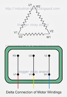
There are three states of Star-Delta starters, a). Star Connected State, b). Open State, and c). Delta Connected State. During starting time Main and Star Contactors remain closed and complete Circuit. In Star Connected State, voltage applied is reduced to 1/√3 of the Line Voltage across each winding. As and when motor attains good rotational speed, say about 90% of full r.p.m. after few seconds, timer connected in starter disconnects Star Contactor first and then connects Delta Contactor. Between these two, Star connected and Delta connected states, circuit becomes open and motor neither remains in Star nor in Delta State. This is called open transition switching. In Delta connected state voltage applied to windings is equal to Line Voltage.Items Required to Make Star Delta Starter
- Three Contactors ( One Main Contactor, One Star Contactor and One Delta Contactor ),
- Over Load Relay ( or OLR )
- Timer,
- Fuse Switch Unit ( or FSU ),
- 2 Pole MCB,
- Fuse,
- Start Push Button ( NO )
- Stop Push Button ( NC )
Working of Star Delta Starter
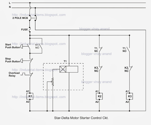
Referring to the Control Circuit of Star Delta Starter shown here, lets understand working ;
- Switching "Start PB" completes Star circuit by switching ON main contactor "K1" and Star contactor "K2" through Timer "T1, NC". Now motor keeps on running in Star configuration.
- Once circuit is completed and main contactor "K1" is activated, one of its "NO" contact point, connected parallel to "Start PB", becomes close and keeps circuit complete by providing a continuous holding even after Push button is released.
- It should remember that the motor remains in Star state configuration till "Timer T1's NC" remains close. After a time delay is reached, Timer T1's NC becomes open, thereby de-activating Star contactor. Immediately after that Timer T1's NO becomes close, thereby activating Delta contactor "K3" to complete Delta circuit. In the time between switching from star state to delta state, which is normally few mili-seconds, circuit becomes open and motor neither remains in Star nor Delta state. Now motor keeps on running normally at full load voltage. To stop motor, "Stop PB" is pressed and circuit becomes open as all contactors are de-activated.
- Both contactors, star & delta contactors, are also electrically isolated from being accidentally operational by providing one another's NC in series with each other. For example, "K3, NC in series with "K2" contactor and "K2, NC" in series with "K3" contactor. Also Over Load protection is provided through OLR.
Advantages of Star Delta Starters
- Simple in Design, &
- Comparatively cheaper.
Dis-Advantages of Star Delta Starters
- Open transition switching,
- Once components are selected and circuit is designed, modifications in design are not possible, &
- Less Torque at the time of starting than during delta configuration operation.
Few other posts seeking your attention are ;


