Saturday, 25 January 2014

Industrial Linear Motion Guides

INTRODUCTION TO LINEAR MOTION GUIDES ;

        Linear Motion Guides are those precision machine elements which are designed with friction less, noise less, vibration free and other working characteristics to permit accurate linear relative motion between two machine members. LM Guides are available in two parts, one is LM bearing or carriage and another is LM shaft or rail over which carriage moves. These guides are made in various shapes, sizes and materials depending upon load, length of travel, speed of travel, space availability and working conditions. Linear Motion Guides find applications in almost every industry from General Purpose Machine Tools to Special Purpose Machine, from Medical Equipment to Aerospace and from Transport to Construction. All the LM guides can be classified broadly into three categories depending upon the type of contact in the guide elements during motion i.e., (i) Sliding Contact, (ii) Rolling Contact and (iii) Magnetic field. 


Classification of Linear Motion Guides ;

            Classification based on technology incorporated to achieve motion or the type of contact in LM Guide elements ;

Types of Linear Motion Guides


1.  Sliding Contact Linear Motion Guides ;

        In these guides, motion takes place because of sliding action between guide elements i.e., LM block and LM guide rails or rods. These are also known as Plain LM Guides. Sliding Contact LM Guides can be further classified in to two sub-categories, depending upon thickness of lubrication film in between sliding surfaces, as given below ;

a)       Thin Lubrication Film Sliding Contact LM Guides ; A partial contact remains in between guide elements as a thin layer of lubricant sweeps in between them during motion. Low friction coefficient materials are used in construction of this category of Guides. Despite of some advantages like simple in design, low cost, etc., these guides, however, least preferred because of certain disadvantages like  high friction, high heat generation, less efficiency, low life, low load carrying capacity, high maintenance.

b)        Hydrostatic LM Guides ; In these types of bearings a thick layer of pressurized fluid holds the carriage and there is no direct contact between the moving elements. To overcome disadvantages of high friction, high heat, etc. pressurized fluid is supplied in between moving elements forcibly from external source, which makes these guides costly because it requires additional unit to supply fluid, not suitable for applications in clean-rooms as there are always chances of leakage of pressurized fluid, etc.

Examples of Sliding Contact Linear Bearings are i) Spline Shaft & Spline Nut, ii) Slide Rails, iii) Lead Screws, etc.

2.    Rolling Contact Linear Motion Guides ; 

       These LM guides consists of balls or cylindrical rollers or wheels of various shapes or profiles which enable smooth and very low frictional motion at fairly high speeds in between carriages and their guides or rails. Despite of being comparatively costly these LM Guides are most preferred because of certain advantages like trouble free operations even at high speeds, compact design, low maintenance, high load carrying capacity, high efficiency, etc.

Examples of Rolling Contact Linear Motion Guides are ;

i)               LM Guide Blocks and Rails, and ii) Ball Screws, in which hardened spherical steel balls keep on circulating in a continuous end-less grooves of carriages while motion. These spherical balls support the carriage over rail or shaft which is firmly fixed to one of the machine members as well as facilitate smooth movement of loads,
iii)       LM Roller Guide Blocks have cylindrical rollers, which facilitate relative movement in between carriage with greater load and rail, and
iv)         Guide Wheels and Rails, in which wheels with a profile usually Circular groove (semi-circle) or V groove in its outer face along circumference is provided. Also a protrusion of similar profile like Guide Wheel’s groove profile in rail is provided which fits into Wheels and guides them. These are preferred where movements of comparatively greater loads at higher velocities are required.

Linear Motion Block
LM Block
Advantages of Rolling Contact LM Guides ;
a)    High Positional Accuracy,
b)   High Efficiency,
c)    High Speed Motion of loads is possible,
d)   High Loads movement is possible, 
e)   Low Noise,
f)     Less Maintenance,
g)    Fairly good Life.

3.  Magnetic Field Linear Motion Guides ; 

       These guides preferably use electromagnets to provide relative linear movements in between two machine members. Their application is limited to only clean rooms in medical and other such similar clean and tidy places as no contact between parts having relative motion eliminates use of any kind of lubrication. Disadvantages like high cost, space constraints, etc. makes them less popular.

Types of Linear Motion Guides

Different types of LM Guides, which falls in any of the above mentioned categories, available in markets have been explained below ;

1.     Linear Motion Block & Rail ; 

          These blocks are highly precise and compact in design, in which 4 rows of steel balls keep on running in continuous end-less paths. The rolling balls remain in firm touch with 4 corresponding raceways on rail and supports block on rail and enable linear movement along the rail. The re-circulation of balls also permits the motion of load along desired length by introducing additional lengths of rails. These guides come in category of rolling contact LM guides and are available with either spherical hardened steel balls or hardened cylindrical rollers, which also re-circulate or guide wheels to achieve rolling action. These are most commonly used guides because of certain advantages like high accuracy, high efficiency, availability, high speed motion, etc.,

2.     Linear Motion Ball Bearings & Shafts ; 

         These are also a type of LM guides which permits linear relative motion. LM Ball Bearings are made in ring shape which carries continuous end-less raceways along its length to guide hardened spherical steel balls during motion. And as the bearings are in ring shape, they deliver motion through cylindrical shafts.  These bearings are available in various shaft sizes and types like closed-type and open-type, with or without flanges, Pillow blocks, etc. Open-type bearings are made cut open along its length to guide shafts mounting on fulcrums. These guides also come in Rolling Contact LM Guides.

3.    Linear Motion Stroke ; 

         These are also made in ring shape like LM bearings, except it has a drilled ball-cage in which holes are arranged spirally along the surface of cage and so the balls are and steel balls do not re-circulate unlike LM bearings. After inserting balls in holes of cage, holes are mechanically deformed through suitable process usually caulking, which narrows holes and cage retains balls and they do not fall. LM Strokes are also rolling contact type and they are suitable for rotational and reciprocating motions. These are used for small distance and high speed movements. 

4.  Linear Motion Spline Nut & Shaft ; 

         A Spline shaft is a round shaft in which a series of continuous equally spaced grooves are cut along the length of the shaft. Spline shafts, therefore, has teeth along its periphery and gives gear like structure when looking from cross-section area.  Thus, spline nut has similar teeth at its internal surfaces, which fits into corresponding grooves on shaft and hence provide stable sliding motion along shaft length. These are Sliding Contact type LM Guides. These are less efficient, they have high friction, low positioning accuracy. Advantages are ; Low Cost, Good Life, Less Maintenance, etc.

5.   Lead Screw ; 

      These screws normally have square threads instead of V threads as they are more efficient. Lead Screws are used to convert rotational motion of screw into linear motion of Nut. Backlash, low efficiency, high wear are the disadvantages of these screws.

6.   Ball Screw ; 

       These guides like Lead Screws convert rotational motion of screw into linear motion of Nut. Unlike lead screws, these are highly efficient because rolling motion of steel balls in between grooves cut in the nut and screw shaft. Steel balls re-circulate in the groove. Wear rate in these guides are much less.

Other LM Guides available in market are ; Ball Spline, Slide Rail, Guide Wheels and some LM Tables with or without drive.

Applications of Linear Motion Guides ;

Some common applications are ;
LM Block / Bearing
LM Block
  • Machine Tools like Horizontal Machining Centres (HMC), Vertical Machining Centres (VMC), CNC machine tools, etc.,
  • Industrial Robots,
  • Medical Equipments,
  • Electronic Equipments,
  • Special Purpose Machineries.

Selection of Linear Motion Guides ;


 LM Guides are selected on the basis of following points ;
  • Load to be moved,
  • Moving Speed of Load,
  • Space Availability,
  • Accuracy,
  • Length of Movement,
  • Efficiency,
  • Working Conditions, &
  • Inter-changeability & Easy Availability


A thought from personal experience ; An LM Block was broken during my service to a Diaper Manufacturing Company. The constraint was that the machine manufacturer was Chinese and spare was not available with us or anywhere in Indian market. It was also not possible to get it delivered from China as it would have taken long time. So, I checked model number of LM Block engraved on it and searched it over internet. I found company's catalog and after comparing all the specifications of LM block with Indian manufacturer, I got part number of local brand Block. I ordered block and in that case rail also had to purchase. Just because of that I had put a point of Easy Availability in Points of Selection.

Guides also need to be protected from dust for which manufacturers provide some accessories like bellows to cover rail and open parts of carriage.


Few other posts seeking your attention are ;


Saturday, 12 October 2013

Star Delta Starter Theory

     Electrical motors have been used in industries for quite a long period of time to convert electrical energy into mechanical energy. Three phase induction motors, also called asynchronous motors, are most extensively used motors in industries because of certain advantages like self starting, robust design, simple construction, less maintenance, efficient and comparatively low cost, though there is a problem of peak starting current associated with these motors. Peak starting current can be up to 5 to 7 times of full load current (flc) and sometimes it may become as high as 10 times of flc. However, the problem of peak starting current remains only for few seconds till the motor attains its speed, this problem may become severe especially with the motors above 10 HP. To deal with the problem of peak starting current or inrush current associated with three phase induction motors, many different starters having different mechanism and principle of operation are used. Star-delta starters are used for motors ranges from 5 hp or 3.5 kW. Star delta starters first configure windings of 3 phase motors in star thereby reduce voltage across each winding and then after few seconds these starters configure windings in delta and motors start run at full load voltage without any difficulty.


Star Delta Connections


 Introduction to Star-Delta Concept 

Star Delta Connections     The magnitude of voltage induced in rotor conductors depends upon the magnetic flux linking with the rotor conductors and the Slip. Slip is the difference between the synchronous speed of the rotating magnetic flux produced from voltage applied to stator windings and the actual rotational speed of the rotor. At the moment of starting, Slip is maximum and decreases as the motor gains speed. Emf, therefore, induced in rotor conductors is high at starting as it is proportional to the Slip. Also magnitude of e.m.f. induced in rotor conductors will become high at the moment of starting, if full rated voltage i.e., line voltage is applied directly to the motor as the strength of the magnetic flux linking with rotor depends upon the voltage applied to the motor.
     Because the impedance of rotor windings being short circuited is very low and voltage induced is very high across windings, the motor current becomes many times of full load current or flc during starting. This high current drawn by the motor may burn motor windings and / or may cause unwanted disturbances in the voltage supply regulation and hence affects other loads adversely connected to the same supply.


   Three phase induction motors are ,therefore, started through appropriate star-delta starters because star-delta starters reduce voltage or start motors at reduced voltage by first configuring windings in star connections to overcome problem of high current surge at starting.


 Working Principle of Star Delta Starter 

     There are three states of Star-Delta starters, a). Star Connected State,  b). Open State, and c). Delta Connected State. During starting time Main and Star Contactors remain closed and complete Circuit. In Star Connected State, voltage applied is reduced to 1/3 of the Line Voltage across each winding. As and when motor attains good rotational speed, say about 90% of full r.p.m. after few seconds, timer connected in starter disconnects Star Contactor first and then connects Delta Contactor. Between these two, Star connected and Delta connected states, circuit becomes open and motor neither remains in Star nor in Delta State. This is called open transition switching. In Delta connected state voltage applied to windings is equal to Line Voltage.


 Items Required to Make Star Delta Starter 

  1. Three Contactors ( One Main Contactor, One Star Contactor and One Delta Contactor ),
  2. Over Load Relay ( or OLR )
  3. Timer,
  4. Fuse Switch Unit ( or FSU ),
  5. 2 Pole MCB,
  6. Fuse,
  7. Start Push Button ( NO )
  8. Stop Push Button ( NC )


Star Delta Starter Power Circuit  of 3 phase induction Motor


Star Delta Control Circuit of 3 phase Induction Motor

 Working of Star Delta Starter 

     Referring to the Control Circuit of Star Delta Starter shown here, lets understand working ;

  • Switching "Start PB" completes Star circuit by switching ON main contactor "K1" and Star contactor "K2" through Timer "T1, NC". Now motor keeps on running in Star configuration.
  • Once circuit is completed and main contactor "K1" is activated, one of its "NO" contact point, connected parallel to "Start PB", becomes close and keeps circuit complete by providing a continuous holding even after Push button is released.
  • It should remember that the motor remains in Star state configuration till "Timer T1's NC" remains close. After a time delay is reached, Timer T1's NC becomes open, thereby de-activating Star contactor. Immediately after that Timer T1's NO becomes close, thereby activating Delta contactor "K3" to complete Delta circuit. In the time between switching from star state to delta state, which is normally few mili-seconds, circuit becomes open and motor neither remains in Star nor Delta state. Now motor keeps on running normally at full load voltage. To stop motor, "Stop PB" is pressed and circuit becomes open as all contactors are de-activated.
  • Both contactors, star & delta contactors, are also electrically isolated from being accidentally operational by providing one another's NC in series with each other. For example, "K3, NC in series with "K2" contactor and "K2, NC" in series with "K3" contactor. Also Over Load protection is provided through OLR.


 Advantages of Star Delta Starters 

  1. Simple in Design, &
  2. Comparatively cheaper.

 Dis-Advantages of Star Delta Starters 

  1. Open transition switching,
  2. Once components are selected and circuit is designed, modifications in design are not possible, &
  3. Less Torque at the time of starting than during delta configuration operation.


Few other posts seeking your attention are ;

  1.    Near Field Communication technology ( NFC )


Sunday, 5 May 2013

Industrial Timing Belts

Timing Belt with Pulleys
Timing Belts
     Belts are used to transmit power from driver shaft to driven shafts using pulleys mounted on the shafts. Timing belts are essentially used where the timing in motion of one machine member has to be precisely maintained with respect to other machine members. Timing belts have teeth, which fits into corresponding grooves on the timing pulleys and thus avoid any slippage. These belts are more quieter in operation & more cheaper than other such mechanisms & can be used at high speeds without any difficulty. These belts are very efficient as well. 
     Timing belts of various teeth profiles, tooth pitches, pitch lengths, widths, materials & strengths suiting different applications and needs are available in the market. Some manufacturers also provide customized special purpose belts on orders.


Structure of Timing Belts

  • Rubber back body protects cords from damage and keeps oil, dirt, grease and other foreign particles away from cords.
  • Timing belts carries equally spaced Cords, which are housed between rubber back body and inner profile teeth. These Cords are made of fibre glass and have high tensile strength, which takes load during machine run and protects belt from breaking under load. Polyurethane (PU) belts carries steel wire rope cords, which provides extra heavy duty strength and are used where belt failure rate is high and where the access to change belt needs more time and efforts. 
  • There are various types of teeth profiles available suiting different operational needs. Inner teeth are covered with nylon fabric which strengthen teeth against wear and abrasion.

Timing Belt Structure


STRUCTURE OF POLYURETHANE TIMING BELT


Nomenclature of Timing Belts

     When replacing belt or placing an order to buy belt from market, a specific naming i.e., nomenclature helps in identifying right size belt. Till late 90s, conventional belts with trapezoidal teeth were in existence and thereafter belts with circular teeth came in market and became popular in industry. For both the belts, different naming scheme is used.

    Trapezoidal Teeth Timing Belt

  1. Nomenclature of conventional belt with Trapezoidal teeth ;

     There are two series available in Trapezoidal profile teeth belts ;

  • Trapezoidal teeth timing belt – Inch Series
Trapezoidal Teeth Timing Belt Nomenclature         To  define  this belt,  we need belt pitch length, tooth pitch and belt  width.  For  example, if ordering a 15  inches long belt,  whose tooth pitch  is  0.2 inch or  1/5  inch  and width  is  0.75 inch or  3/4 inch  then  nomenclature  will  be  "150 XL 075".  Various  standard tooth  pitches  available are given  in the following table. Tooth pitches can be selected from the following table.


Trapezoidal Teeth Timing Belt Nomenclature


  • Trapezoidal teeth timing belt – Metric Series
Timing Belt Nomenclature Metric Series
          To  define  this belt,  we need belt pitch length, tooth pitch and belt  width.  For  example, if ordering a 1500 mm long belt,  whose tooth pitch  is  5 mm and width  is  40 mm then  nomenclature  will  be  "1500 T5 40".  Various  standard tooth  pitches  available are given  in the following table along with their  abbreviations. Tooth pitches can be selected from the following table.


Timing Belt Nomenclature Metric Series

There is slight difference in teeth of belts having pitch start from T and AT like teeth height, etc.


       2.    Nomenclature of timing belt with curvilinear teeth ;


Following types of circular or curvilinear teeth are available ;

  • HTD (High Torque Drive) or conventional curvilinear teeth timing belt ;
HTD Timing Belt Nomenclature 
           To define this belt, we need belt pitch length, tooth pitch and belt width. For example, if ordering a 1396 mm long belt, whose tooth pitch is 8 mm and width is 30 mm then nomenclature will be "1396-8M-30".  Belts of various tooth pitches can be selected. Available tooth pitches are 2M, 3M, 5M, 8M, 14M & 20M. 

HTD timing belt

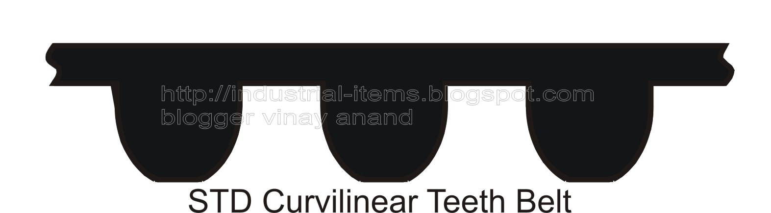
  • STD (Super Torque Drive) or modified curvilinear teeth timing belt ;
STD Curvillinear Timign Belt           To define this belt, we need belt pitch length, tooth pitch and belt width. For example, if ordering a 896 mm long belt, whose tooth pitch is 8 mm and width is 30 mm then nomenclature will be "896-S8M-30".  Belts of various tooth pitches can be selected. Available tooth pitches are 2M, 3M, 5M, 8M, 14M & 20M.


    Synchronous Belt
  • Belts with teeth at both sides ;
.         Belts with teeth at both sides are also available. These belts come in use, when drive from motor or gear box has to give to more than one timing pulley rotating in opposite directions. Again available tooth pitches are 2M, 3M, 5M, 8M, 14M & 20M.


        Sometimes when numbers marked on belts are erased due to friction, it becomes difficult to identify belt because it is neither easy nor reliable to measure belt's length as it elongates extensively during time of use and also from the portion it breaks. In such case, we can measure tooth pitch and count the number of teeth. The multiplication of both will give us belt length. Width can be measured easily.

       Open ended belts are also provided by manufacturers which are cut as per size required in zig-zag format called fingers, from both the ends and jointed with the help of punching machine or press machine under application of heat, which is called finger joint. Apart from open ended belts, different manufacturers make special purpose belts as per need and demand of industry. 


Advantages of timing belts ;

  1. Timing belts are highly precise & efficient because these belts do not slip like flat belts or V-belts.
  2. As there is no metal to metal contact like gears, timing belts are quieter and wear less during operation over the period of time. Also no lubrication is required.
  3. Strong, light weight & cheaper.
  4. Can be used for high speed applications.
  5. Timing Belts can be used for comparatively longer centre distances between shafts than chain drives.

Care for Timing Belts ;

  1. In operation (while doing preventive maintenance of the machine, technicians should take care of following points related to timing belts to avoid frequent breaking) ;

  • Environment surrounding belts should be clean free from oil, grease, moisture, dirt and other foreign particles.
  • Belts wearing from one side that may be because of mis-alignment of pulleys. Pulleys must be re-aligned in such cases.
  • When the pulley is too small and the centre distance is also too small then idler must use at the slack side to increase teeth engagement on the smaller pulley and to avoid breaking.
  • When belts break too frequently then its tension must be re-adjusted.
  • Remove belts and never let belts run idler, if some operation has to stop in machine for a long period of time as it also leads to wear and tear.

     2.  In storage ;
  • Store in cleaner place free from oil, grease, moisture, dirt and other foreign particles.
  • Do not keep belts in twisted position while storing belts.
  • Do not put excessive loads on belts as its teeth may deform, which may affect normal working.


Few other posts seeking your attention ;
     More at ; Scientific Laws
     More at ; Bhakti Sangrah